Experiment #1: D.C. Circuits
实验 #1:直流电路
Reference: Simpson Ch 1, Appendices A & C
Objective: To become familiar with Ohm's law, Kirchoff's laws and their use in analyzing basic D.C. Circuits containing only resistors.
目标:熟悉欧姆定律、基尔霍夫定律及其在分析仅含电阻的直流电路中的应用。
Procedure: Digital multimeters will be used for the voltage and current measurements. Refer to the description of the multimeter in the lab manual for further details. The voltage will be obtained from the Pasco power supply (refer to the instructions). Note that part IIIB can be done outside of lab.
步骤:将使用数字万用表进行电压和电流的测量。请参阅实验室手册中关于万用表的描述以获取更多细节。电压将来自Pasco电源(请参阅说明)。请注意,第二部分III可以在实验室外完成。
I. Series Circuits:
A. Wire the circuit shown in Figure 1.
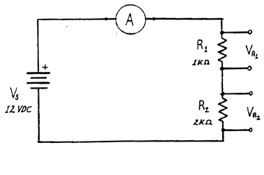
- Measure and record the values for the current, the voltage
across R1 (VR1) , the voltage across R2 (VR2), and the supply voltage. Remove, measure and record the values of your resistors.
测量并记录电流、R1两端的电压(VR1)、R2两端的电压(VR2)以及电源电压。拆除并测量记录你的电阻器的值。
- In order to have the meters read in the "forward" direction the
connections to the + and - meter terminals must be one of the
two possibilities.
- Sketch your circuit showing its working connections
画出你的电路及其工作连接
- Justify the connections in terms of Ohm's law and the
direction of current flow.
根据欧姆定律说明连接方式,并说明电流的方向。
为了使仪表指针向‘正方向’移动,仪表的 '+' 和 '-' 接线端必须采用其中一种可能的连接方式。 - Sketch your circuit showing its working connections
- Calculate the current based on the resistance values (see the
text for a color code chart) and compare it with the result from
part 1. If there is a difference, is it reasonable?
根据电阻值(见文本中的颜色代码表)计算电流,并与第1部分的结果进行比较。如果存在差异,是否合理?
I. 串联电路:A. 按图1所示连接电路。图1 B. 计算R1与R2串联时的等效电阻Req,并测量电流。将结果与部分A的结果进行比较。这种比较是否合理?
II. Parallel Circuits
A. Wire the circuit shown in Figure 2.
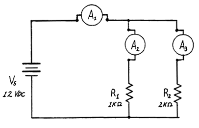
- Measure and record the voltages across R1 and R2 and the power supply. Record your resistor values. Show on a
sketch the connections of the + and - meter leads.
测量并记录R1和R2两端的电压以及电源电压。记录你的电阻值。在草图上标出+和-表笔的连接方式。
- Insert the milliammeter into the circuit in each of the locations
(A1), (A2), and (A3) in turn. Record each reading, and show on a
sketch the orientation of the + and - connections.
将毫安表依次插入电路的每个位置(A1)、(A2)和(A3)。记录每个读数,并在草图上标明+和-连接的方向。
- Compare the value of (I1) with those of (I2) and (I3). Is the
comparison reasonable in terms of circuit theory?
将(I1)的值与(I2)和(I3)的值进行比较。这种比较在电路理论方面是否合理?
II. 并联电路 A. 如图2所示连接电路。图2 B. 计算R1与R2并联的等效电阻Req,并测量电流。将其结果与上面第2部分的结果进行比较。这种比较是否合理?
III. More Complicated Circuit
A.Set up the circuit shown in Figure 3.
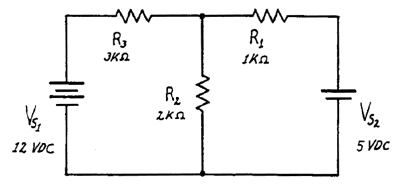
- Double-check your wiring to be sure it is as the schematic
shows.
请检查接线是否与原理图一致。
- Measure and record the voltages across each resistor. Make a
sketch showing the polarity of the voltages as indicated by the
polarity of the voltages as indicated by the voltmeter
connections. From the voltage across each R, calculate the
current through the resistors.
测量并记录每个电阻器两端的电压。绘制一个示意图,显示由电压表连接指示的电压极性。根据每个电阻器上的电压,计算通过电阻器的电流。
III. 更复杂的电路 A. 搭建图3所示的电路。图3 B. 理论计算每个电阻中流过的电流(包括方向),并将结果与部分A中得到的结果进行比较。这种比较是否合理?
| Sample data and setup
样本数据和装置 |
参考:Simpson 第1章,附录A和C
索引
HyperPhysics ***** 物理学 3500
返回