Bilingual edition: English is preserved and Chinese follows each unit. Terminology uses the confirmed v20260916 glossary; automated semantic review remains traceable.
中英双语版:英文原文完整保留,中文紧随对应单元;术语采用 v20260916 确认表,自动语义审校结果可追溯。

Truth Tables

真值表

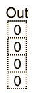
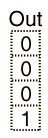
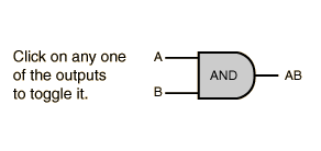
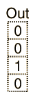
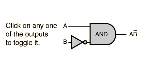
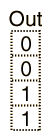
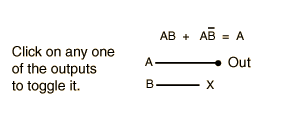
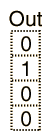
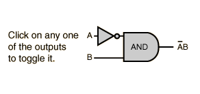
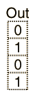
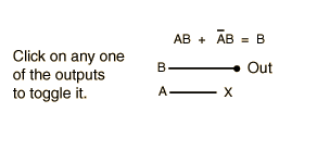
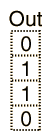
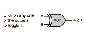
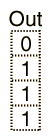
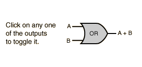
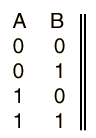
A truth table shows how a logic circuit's output responds to various combinations of the inputs, using logic 1 for true and logic 0 for false. All permutations of the inputs are listed on the left, and the output of the circuit is listed on the right. The desired output can be achieved by a combination of logic gates. A truth table for two inputs is shown, but it can be extended to any number of inputs. The input columns are usually constructed in the order of binary counting with a number of bits equal to the number of inputs.

真值表显示逻辑电路的输出如何响应各种输入组合,使用逻辑1表示真,逻辑0表示假。所有输入的排列组合列在左边,而电路的输出列在右边。通过逻辑门的组合可以实现期望的输出。图中展示了一个两输入的真值表,但它可以扩展到任何数量的输入。输入列通常按照二进制计数的顺序排列,位数等于输入的数量。
Digital Logic Theorems
数字逻辑定理
Digital Logic Functions
数字逻辑函数
Index

Electronics concepts

Digital Circuits
索引 电子学概念 数字电路
 
HyperPhysics*****Electricity and magnetism
HyperPhysics ***** 电磁学
R Nave
Go Back
返回


Truth Tables

真值表

A truth table shows how a logic circuit's output responds to various combinations of the inputs, using logic 1 for true and logic 0 for false. All permutations of the inputs are listed on the left, and the output of the circuit is listed on the right. The desired output can be achieved by a combination of logic gates. A truth table for two inputs is shown, but it can be extended to any number of inputs. The input columns are usually constructed in the order of binary counting with a number of bits equal to the number of inputs.

真值表显示逻辑电路的输出如何响应各种输入组合,使用逻辑1表示真,逻辑0表示假。所有输入的排列组合列在左边,而电路的输出列在右边。通过逻辑门的组合可以实现期望的输出。图中展示了一个两输入的真值表,但它可以扩展到任何数量的输入。输入列通常按照二进制计数的顺序排列,位数等于输入的数量。
Digital Logic Theorems
数字逻辑定理
Digital Logic Functions
数字逻辑函数
Index

Electronics concepts

Digital Circuits
索引 电子学概念 数字电路
 
HyperPhysics*****Electricity and magnetism
HyperPhysics ***** 电磁学
R Nave
Go Back
返回


Truth Tables

真值表

A truth table shows how a logic circuit's output responds to various combinations of the inputs, using logic 1 for true and logic 0 for false. All permutations of the inputs are listed on the left, and the output of the circuit is listed on the right. The desired output can be achieved by a combination of logic gates. A truth table for two inputs is shown, but it can be extended to any number of inputs. The input columns are usually constructed in the order of binary counting with a number of bits equal to the number of inputs.

真值表显示逻辑电路的输出如何响应各种输入组合,使用逻辑1表示真,逻辑0表示假。所有输入的排列组合列在左边,而电路的输出列在右边。通过逻辑门的组合可以实现期望的输出。图中展示了一个两输入的真值表,但它可以扩展到任何数量的输入。输入列通常按照二进制计数的顺序排列,位数等于输入的数量。
Digital Logic Theorems
数字逻辑定理
Digital Logic Functions
数字逻辑函数
Index

Electronics concepts

Digital Circuits
索引 电子学概念 数字电路
 
HyperPhysics*****Electricity and magnetism
HyperPhysics ***** 电磁学
R Nave
Go Back
返回


Truth Tables

真值表

A truth table shows how a logic circuit's output responds to various combinations of the inputs, using logic 1 for true and logic 0 for false. All permutations of the inputs are listed on the left, and the output of the circuit is listed on the right. The desired output can be achieved by a combination of logic gates. A truth table for two inputs is shown, but it can be extended to any number of inputs. The input columns are usually constructed in the order of binary counting with a number of bits equal to the number of inputs.

真值表显示逻辑电路的输出如何响应各种输入组合,使用逻辑1表示真,逻辑0表示假。所有输入的排列组合列在左边,而电路的输出列在右边。通过逻辑门的组合可以实现期望的输出。图中展示了一个两输入的真值表,但它可以扩展到任何数量的输入。输入列通常按照二进制计数的顺序排列,位数等于输入的数量。
Digital Logic Theorems
数字逻辑定理
Digital Logic Functions
数字逻辑函数
Index

Electronics concepts

Digital Circuits
索引 电子学概念 数字电路
 
HyperPhysics*****Electricity and magnetism
HyperPhysics ***** 电磁学
R Nave
Go Back
返回


Truth Tables

真值表

A truth table shows how a logic circuit's output responds to various combinations of the inputs, using logic 1 for true and logic 0 for false. All permutations of the inputs are listed on the left, and the output of the circuit is listed on the right. The desired output can be achieved by a combination of logic gates. A truth table for two inputs is shown, but it can be extended to any number of inputs. The input columns are usually constructed in the order of binary counting with a number of bits equal to the number of inputs.

真值表显示逻辑电路的输出如何响应各种输入组合,使用逻辑1表示真,逻辑0表示假。所有输入的排列组合列在左边,而电路的输出列在右边。通过逻辑门的组合可以实现期望的输出。图中展示了一个两输入的真值表,但它可以扩展到任何数量的输入。输入列通常按照二进制计数的顺序排列,位数等于输入的数量。
Digital Logic Theorems
数字逻辑定理
Digital Logic Functions
数字逻辑函数
Index

Electronics concepts

Digital Circuits
索引 电子学概念 数字电路
 
HyperPhysics*****Electricity and magnetism
HyperPhysics ***** 电磁学
R Nave
Go Back
返回


Truth Tables

真值表

A truth table shows how a logic circuit's output responds to various combinations of the inputs, using logic 1 for true and logic 0 for false. All permutations of the inputs are listed on the left, and the output of the circuit is listed on the right. The desired output can be achieved by a combination of logic gates. A truth table for two inputs is shown, but it can be extended to any number of inputs. The input columns are usually constructed in the order of binary counting with a number of bits equal to the number of inputs.

真值表显示逻辑电路的输出如何响应各种输入组合,使用逻辑1表示真,逻辑0表示假。所有输入的排列组合列在左边,而电路的输出列在右边。通过逻辑门的组合可以实现期望的输出。图中展示了一个两输入的真值表,但它可以扩展到任何数量的输入。输入列通常按照二进制计数的顺序排列,位数等于输入的数量。
Digital Logic Theorems
数字逻辑定理
Digital Logic Functions
数字逻辑函数
Index

Electronics concepts

Digital Circuits
索引 电子学概念 数字电路
 
HyperPhysics*****Electricity and magnetism
HyperPhysics ***** 电磁学
R Nave
Go Back
返回


Truth Tables

真值表

A truth table shows how a logic circuit's output responds to various combinations of the inputs, using logic 1 for true and logic 0 for false. All permutations of the inputs are listed on the left, and the output of the circuit is listed on the right. The desired output can be achieved by a combination of logic gates. A truth table for two inputs is shown, but it can be extended to any number of inputs. The input columns are usually constructed in the order of binary counting with a number of bits equal to the number of inputs.

真值表显示逻辑电路的输出如何响应各种输入组合,使用逻辑1表示真,逻辑0表示假。所有输入的排列组合列在左边,而电路的输出列在右边。通过逻辑门的组合可以实现期望的输出。图中展示了一个两输入的真值表,但它可以扩展到任何数量的输入。输入列通常按照二进制计数的顺序排列,位数等于输入的数量。
Digital Logic Theorems
数字逻辑定理
Digital Logic Functions
数字逻辑函数
Index

Electronics concepts

Digital Circuits
索引 电子学概念 数字电路
 
HyperPhysics*****Electricity and magnetism
HyperPhysics ***** 电磁学
R Nave
Go Back
返回


Truth Tables

真值表

A truth table shows how a logic circuit's output responds to various combinations of the inputs, using logic 1 for true and logic 0 for false. All permutations of the inputs are listed on the left, and the output of the circuit is listed on the right. The desired output can be achieved by a combination of logic gates. A truth table for two inputs is shown, but it can be extended to any number of inputs. The input columns are usually constructed in the order of binary counting with a number of bits equal to the number of inputs.

真值表显示逻辑电路的输出如何响应各种输入组合,使用逻辑1表示真,逻辑0表示假。所有输入的排列组合列在左边,而电路的输出列在右边。通过逻辑门的组合可以实现期望的输出。图中展示了一个两输入的真值表,但它可以扩展到任何数量的输入。输入列通常按照二进制计数的顺序排列,位数等于输入的数量。
Digital Logic Theorems
数字逻辑定理
Digital Logic Functions
数字逻辑函数
Index

Electronics concepts

Digital Circuits
索引 电子学概念 数字电路
 
HyperPhysics*****Electricity and magnetism
HyperPhysics ***** 电磁学
R Nave
Go Back
返回