RC High Pass FilterRC 高通滤波器
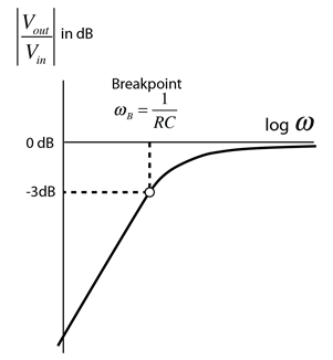
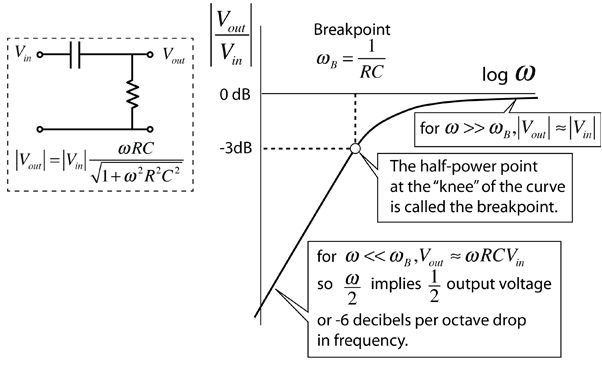
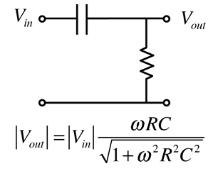
Since capacitive reactance decreases with frequency, the RC circuit shown discriminates against low frequencies. The circuit is an AC voltage divider with an output which falls off at low frequencies at the rate of 6 dB per octave. 由于容抗随频率升高而减小,所示的RC电路对低频信号有衰减作用。该电路是一个交流电压分压器,其输出在低频段以每 octave 6 dB 的速率下降。
It is typical to plot filter response curves in decibels, which are defined in terms of power or intensity ratios. They are defined as 10 times the logarithm to the base 10 of the power ratio. The electric power dissipated in a resistor is proportional to the voltage squared, so if you are using a voltage ratio instead, the number of decibels is 20 log10(Vout/Vin).
通常以分贝为单位绘制滤波器响应曲线,这些分贝值是基于功率或强度比定义的。它们定义为10乘以以10为底的对数的功率比。电阻中消耗的电功率与电压平方成正比,因此如果使用电压比,分贝数为20 log 10 (V_out / V_in)。 |
Index Capacitance concepts Inductance concepts 电容概念 感应概念 | |||||
|
Go Back
返回 |
RC High Pass Filter DetailsRC高通滤波器细节
![]()
|
Index Capacitance concepts Inductance concepts 电容概念 感应概念 | |||
|
Go Back
返回 |
RC High Pass Filter CalculationRC高通滤波器计算
Since capacitive reactance decreases with frequency, the RC circuit shown discriminates against low frequencies. The circuit is an AC voltage divider with an output which falls off at low frequencies at the rate of 6 dB per octave. 由于容抗随频率升高而减小,所示的RC电路对低频信号有衰减作用。该电路是一个交流电压分压器,其输出在低频段以每 octave 6 dB 的速率下降。
One approach to the design of a high-pass filter is to establish a frequency "breakpoint" or "knee" by choice of the resistance and capacitance. The design calculation works by clicking on the desired quantity in the expression. Enter the necessary data and then click on the quantity you wish to calculate. Default values will be entered for unspecified quantities, but all quantities may be changed. After the filter has been designed, the amount of attenuation in decibels at any frequency can be evaluated by the separate calculation below. Once you get well below the breakpoint frequency, the amount of attenuation will increase by about 6dB per octave, which you can confirm with that exploratory calculation. 转折点 = 1/(电阻 × 电容)
设计高通滤波器的一种方法是通过选择电阻和电容来确定一个频率“转折点”或“膝点”。设计计算通过点击表达式中的所需量来进行。输入必要的数据,然后点击您希望计算的量。未指定的量将输入默认值,但所有量都可以更改。滤波器设计完成后,可以通过下面的单独计算评估任何频率下的衰减量(以分贝为单位)。一旦频率远低于转折频率,衰减量将每 octave 增加约 6dB,您可以使用该探索性计算来确认。和频率 = x10^ Hz = kHz = MHz 中文译文中的待填/计算数值依次对应:1:fb 2:fp 3:fk 4:fm。实际数值以上方原输入框为准。 |
Index Capacitance concepts Inductance concepts 电容概念 感应概念 | ||||
|
Go Back
返回 |