|
Index Electronics concepts Digital circuits Data Transfer J-K Flip-Flop Applications Reference Tocci Digital Systems, Sec 5-19 索引 电子学概念 数字电路 数据传输 J-K 触发器 应用 参考 Tocci 数字系统,第5-19节 | ||||
|
Go Back
返回 |
BCD or Decade CounterBCD或十进制计数器
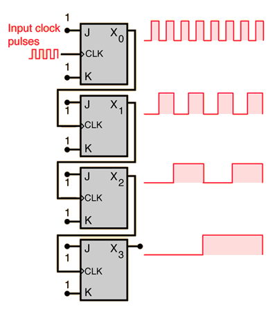
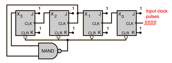
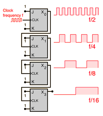
![]() A BCD counter or decade counter can be constructed from a straight binary counter by terminating the "ripple-through" counting when the count reaches decimal 9 (binary 1001). Since the next toggle would produce 1010, that drives both X1 and X3 high, and since they are the inputs to the NAND gate, the output of the NAND goes low. This zero output to the asynchronous clear line will clear the registers and start the count over after 9. 一个BCD计数器或十进制计数器可以通过一个直接二进制计数器构造,当计数达到十进制9(二进制1001)时终止“级联计数”。由于下一次翻转会产生1010,这会使得X1和X3同时变高,而它们是NAND门的输入,因此NAND门的输出会变低。这个低电平输出将异步清零线置零,从而清空寄存器并从9开始重新计数。
|
Index Electronics concepts Digital circuits Data Transfer J-K Flip-Flop Applications Reference Tocci Digital Systems, Sec 7-2 索引 电子学概念 数字电路 数据传输 J-K 触发器 应用 参考 Tocci 数字系统,第7-2节 | ||
|
Go Back
返回 |
|
Index Electronics concepts Digital circuits Data Transfer J-K Flip-Flop Applications Reference Tocci Digital Systems, Sec 5-19 索引 电子学概念 数字电路 数据传输 J-K 触发器 应用 参考 Tocci 数字系统,第5-19节 | |||
|
Go Back
返回 |
Frequency Counter频率计数器
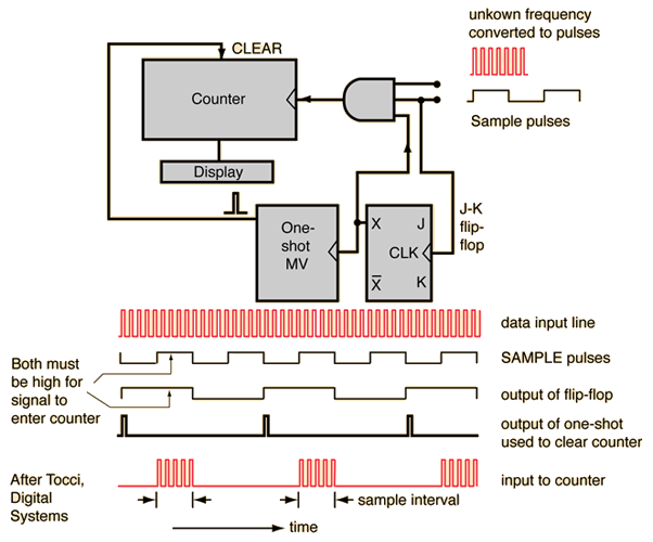
A frequency counter can be made from a binary counter and a decoder/display unit. In the schematic below an AND gate is used as an input device. The unknown frequency is applied to one input of the AND and sample pulses of precise time interval are applied to the other. When the sample pulse is high, the input signal is transferred to the counter. The number of counts divided by the sample time interval gives the frequency. In the design shown, there is another practical element: after the count is done, there must be time to view the result on the display, so a third input to the AND gate is taken from a J-K flip-flop. The input reaches the counter only when both the sample pulse and the J-K flip-flop are high (counts are collected on alternate sample pulses). This provides an interval when the frequency is displayed. On each positive-going edge of the J-K, a one-shot multivibrator is triggered to send a pulse for resetting the counter. 一个频率计数器可以由二进制计数器和解码器/显示单元组成。在下面的原理图中,一个与门被用作输入设备。未知频率信号施加于与门的一个输入端,而精确时间间隔的采样脉冲施加于另一个输入端。当采样脉冲为高电平时,输入信号被传输到计数器。将计数次数除以采样时间间隔即可得到频率。在所示设计中,还有一个实际元件:在计数完成后,必须有时间查看显示结果,因此与门的第三个输入端来自一个J-K触发器。只有当采样脉冲和J-K触发器同时为高电平时,输入才会被传输到计数器(计数是在交替的采样脉冲上进行的)。这提供了显示频率的时间间隔。在每个J-K的正跳变边沿,一个单稳多谐振荡器被触发,以发送一个重置计数器的脉冲。
![]()
|
Index Electronics concepts Digital circuits Sequential Operations J-K Flip-Flop Applications Reference Tocci Digital Systems, Sec 7-16 索引 电子学概念 数字电路 顺序操作 J-K 触发器 应用 参考 Tocci 数字系统,第7-16节 | ||
|
Go Back
返回 |